

The problem: thermal performance that betrays product intent
Design teams pick a PTC heater for its self-regulating promise, but delivered assemblies often miss temperature targets, overshoot, or die early. The gap sits between datasheet claims and system realities: thermal coupling, ambient swings, control-loop latency, and mechanical integration. You might be evaluating an incubator heating element or a compact module for wearable warming; the same specification traps apply. Solve the mismatch up front or accept rework cycles and missed timetables.
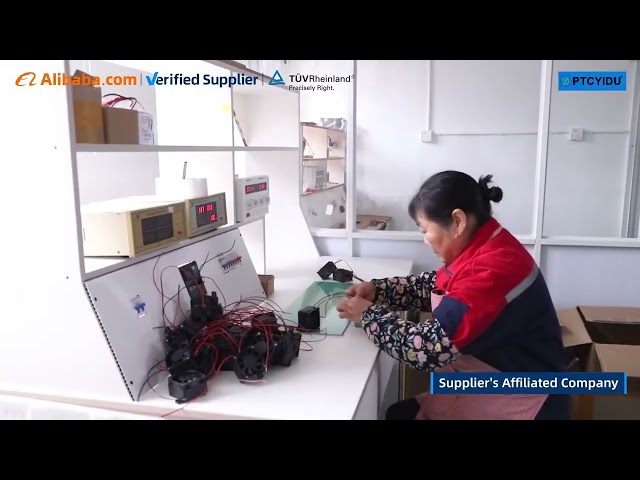
Why it fails: pinpointing root causes
Manufacturing environments and embedded systems generate subtle stressors. Power density and substrate conduction create local hotspots. TCR nonlinearity shifts operating points as the element ages. Bad PCB thermal vias turn a benign module into a thermal sink. Control software with long loop periods amplifies set-point drift. EMI coupling can alter sensor readings and trigger false thermal trips. You need to treat the heater as a subsystem, not a plug-and-play part.
Specification checklist — metrics that cut risk
Use measurable criteria. Target numbers, not promises.
– Rated power and watt density (W/cm²) at the intended mounting condition.
– Thermal resistance (Rth) and time constant (τ) with specified mass and TIM.
– Maximum continuous surface temperature (Tmax) and safe short-term excursion temperature.
– Temperature coefficient of resistance (TCR) and stabilization behavior over cycles.
– Voltage/current limits and inrush behavior; PTCs can clamp current but still have start-up overshoot.
– Mechanical mounting specs: planar tolerance, recommended TIM, screw torque.
– Environmental ratings: IP, salt fog, vibration spec, and RoHS/REACH where applicable.
– Certifications and test reports: thermal cycling, shock, and UL/IEC safety data.
Common mistakes that wreck schedules
Teams routinely oversize for margin and under-derate for thermal coupling. Oversizing increases cost and inertia; underspecing yields hotspot failure. Ignoring the thermal interface material choice is a fast route to higher junction temperatures. Trusting a single-point temperature sensor without validating spatial gradients invites false stability. Finally, assume the datasheet test fixture differs from your assembly—verify with a prototype and telemetry.
Alternatives and real-world validation
Ceramic PTCs, polymer PTCs, cartridge heaters, and flexible silicone heaters each solve different problems. Ceramic PTCs give stable, compact heating with predictable thermal mass; polymer PTCs offer softer curves and lower cost; cartridge heaters scale power but need active control. For egg incubation and hatchery contexts, ceramic elements are commonly deployed at commercial scale—Iowa State University and regional hatcheries in Iowa document controlled-hatch benefits when uniformity is prioritized—see practical implementations like ceramic heat element for egg incubator. Choose the tech that aligns with your control bandwidth and form-factor constraints.
Integration roadmap — practical steps to execution
1) Define target thermal profile (set-point, allowed gradient, warm-up time). 2) Pick candidate modules using the checklist metrics. 3) Run a compact CFD or lumped-parameter thermal simulation to validate design points. 4) Prototype with full mechanical stack: TIM, mounting, sensor placement, and cabling. 5) Implement a control loop (fast PID or on-chip hysteresis) and log telemetry for multiple ambient cases. 6) Iterate on mounting and TIM to hit Rth targets. 7) Harden with EMC and safety tests before scaling.
Synthesis — pick precise parts, instrument aggressively, iterate fast
PTC modules succeed when engineers treat heat as a systems problem: quantify, simulate, prototype, and instrument. Target metrics, avoid the usual mounting and sensor traps, and validate with real-world test rigs. For modular supply and proven element designs that align with these steps, consider suppliers with transparent data and tested assemblies such as PTCYIDU to streamline the path from spec to reliable thermal behavior.