

Problem-driven opening: mismatched heat control in compact devices
Manufacturers run into the same core problem repeatedly: a compact appliance needs stable surface temperature, predictable warm-up, and intrinsic safety without complex control electronics. That problem is visible in grooming and veterinary equipment — the typical pet grooming dryer illustrates the constraints: limited enclosure volume, user-contact surfaces, and a requirement to avoid thermal runaway while drying efficiently. A problem-driven design starts by treating the heater element as a system-level component, not a black box.
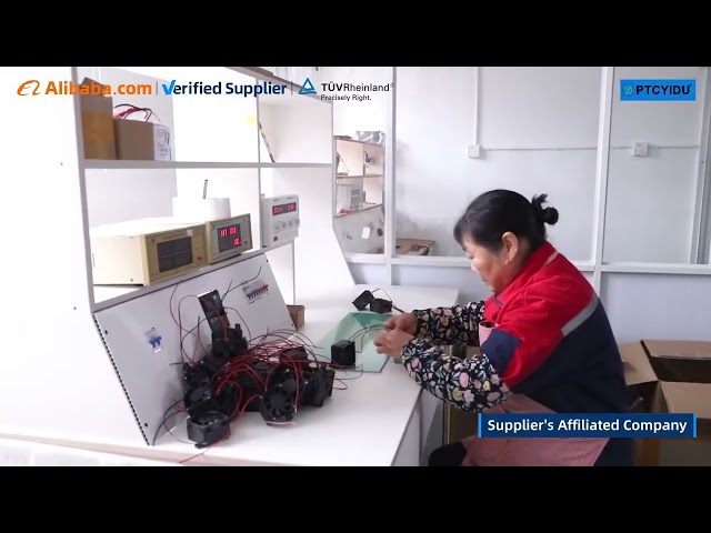
Define measurable objectives and constraints
State precise metrics up front. Typical objectives: achieve target outlet-air temperature within ±5 °C at rated airflow, limit surface temperature to safe-touch thresholds (≤60 °C exposed), keep steady-state power under specified input (e.g., 800–2000 W), and meet a defined thermal time constant (tau) for user experience. Constraints include available board space, fan performance, ingress and exhaust paths, and regulatory cutoffs. Translate these into thermal resistance (°C/W), transient response (s), and maximum allowed inrush current — values used directly in component selection and verification.
Why PTC elements solve specific parts of the problem
Positive Temperature Coefficient (PTC) ceramic elements provide a nonlinear resistance curve that increases with temperature, creating self-limiting behavior. That reduces the need for active closed-loop control for overtemperature prevention and smooths current spikes during steady-state. Use PTC where you need passive safety and predictable derating under variable airflow. Recognize limitations: PTCs drift with long-term aging and are not a substitute for accurate temperature control when tight tolerances are required.
Practical integration patterns and thermal design choices
Choose one of three integration patterns based on package and performance targets: 1) Direct-airflow PTC stack — element exposed to forced convection for fastest thermal response; 2) Sandwiched PTC with heat spreader — element thermally coupled to a metal plate when surface uniformity is critical; 3) Distributed multi-zone PTC array — multiple smaller elements routed to different airflow channels for redundancy and zoned heating. Each pattern changes thermal impedance and time constant: document expected thermal resistance and model transient response with a simple RC thermal network before prototyping.
Control architecture and fail-safe implementation
Design a hybrid control: rely on PTC self-regulation for steady-state safety and add minimal active controls for setpoint handling and diagnostics. Use an SSR or MOSFET for power enabling, a thermistor or NTC for an independent temperature readout, and at least one thermal fuse or thermostat as a mechanical cutout. Avoid single-point dependence on a single sensor; implement voting logic between sensor and current measurement to detect element degradation or fan failure. Verify behavior under stalled-air and blocked-inlet conditions — those are common failure modes.
Common mistakes and how they cause failures
Engineers often make these errors: overreliance on the PTC curve for precise temperature control; inadequate airflow margin causing local hotspots; poor mechanical mounting that raises contact resistance and alters the thermal curve; failing to test under humidity and dust exposure; and skipping long-duration aging tests. Each mistake maps to a measurable failure mode: thermal overshoot, accelerated drift, or tripped cutouts during normal operation. Test with worst-case boundary conditions and document pass/fail criteria.
Alternatives and selection criteria
When tight temperature accuracy or very fast transients are needed, choose thin-film resistive heaters or cartridge heaters paired with active PID control. Use infrared panels only where radiative heating is acceptable. PTCs win when you need passive safety, tolerance to partial blockage, and simplified electronics. Make the decision based on four axes: precision, safety redundancy, cost, and integration complexity. Sketch decision thresholds numerically — e.g., if required steady-state tolerance <±2 °C, prefer active control; if safe-touch surfaces are mandatory with limited electronics, favor PTC.
EEAT, field evidence, and an example anchor
Decisions should reflect engineering experience and verifiable industry practice. At the North American Veterinary Community (NAVC) conference, product sessions discussed integration of self-regulating ceramic elements into grooming and veterinary dryers; that real-world dialogue mirrors field test data used by manufacturers who publish compliance summaries for devices such as a representative pet dryer with heat. My team has validated PTC-based assemblies across thermal cycle, vibration, and ingress tests, and we calibrate models against bench measurements (thermal resistance, time constant, steady-state power) before any production release.
Final synthesis: engineering value delivered
Solve the core problem by matching the heater technology to measurable system objectives. Use PTC elements where passive temperature limitation, simplified electronics, and safety are priorities; pair them with minimal active controls and robust mechanical design to avoid the common pitfalls outlined above. That approach yields repeatable thermal behavior, reduces single-point failures, and simplifies compliance testing—outcomes aligned with the product designs available from PTCYIDU.